Wiring a Switch

In this example, we have a 2-car garage that we want to convert half of it to a workshop. We're feeling spunky so we put a wall up right down the middle.
Let's assume all we have right now are the machines identified in the drawing. The table saw and the jointer are both 240V, everything else is 120V. The plan is to make the electrical rough-in as flexible as possible for future expansion and everyday workflow. The TS, jointer and DC will all be on their own circuits.
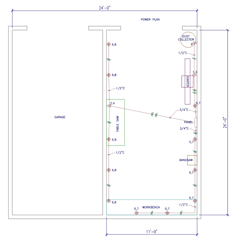
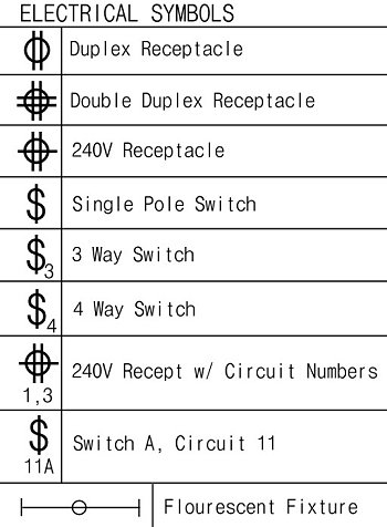
The circle with the hashtag in it is a double receptacle; the one with just 2 parallel lines is a single receptacle. Slash marks on the conduit runs represent wires, the long ones are neutrals, the shorter are hots. I did not include any ground wires in this. A ground wire is a long slash with a dot at the end of it. The numbers near the devices are circuit numbers and correspond to their location in the panel. This is for a 120/240 single phase system.
The conduit sizes are the minimum I would suggest. If I was doing this, all the branch conduits in the above drawing would be 3/4". The double receptacles will each be on their own circuit. This gives you the ability to plug two heavier loads into the same box without tripping a breaker. If you want to really dress it up, mark every box and device with their respective circuit numbers. I included a neutral with each 240V dedicated load because some require it.
Post #2:
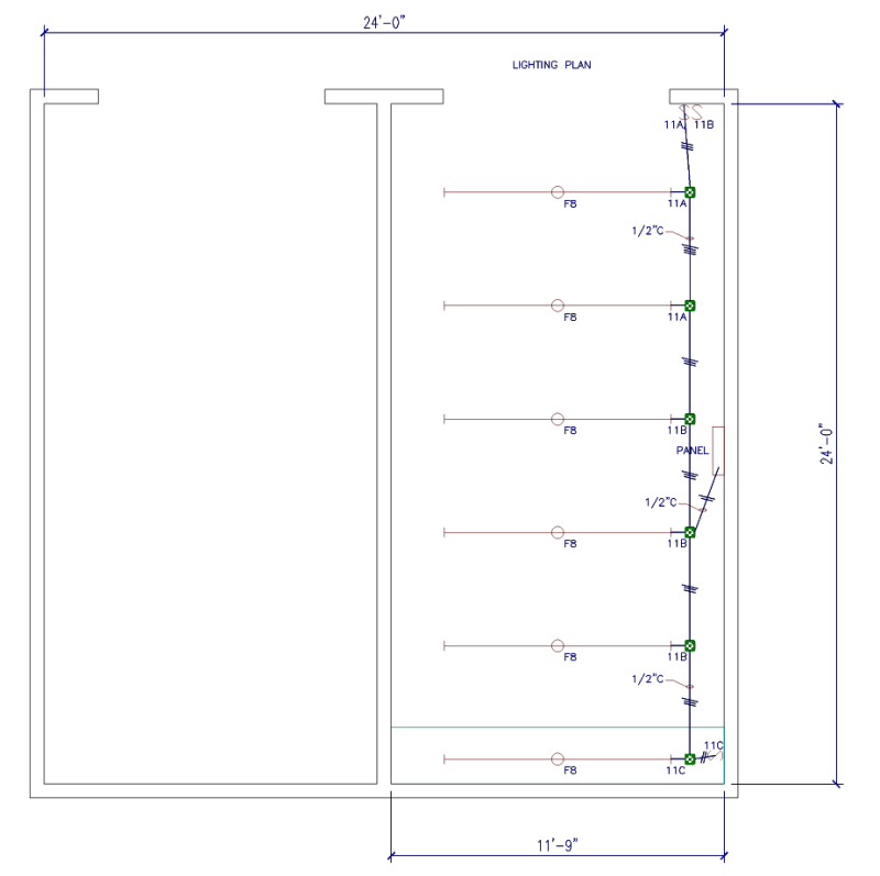
Here, we have ceiling mounted, 8' fluorescent fixtures, spaced 4' apart. There are two switches at the door and another at the workbench. If you look at the end of the fixtures you will see "11A", "11B" or "11C". The "A", "B" and "C" relate to the switch that will operate these fixtures. The switches will have the designation next to them. "S" is switch.
You do not have to split it up like this but the lighting controls should be figured around your work habits. You may not always want all the lights on at the same time. And if you want to add another fixture over the workbench (like when your eyes get bad ), you can easily do so. The junction boxes at the end of every fixture simplify expansion. You can pull through all the fixtures but you won't be happy when you want to change something.
Just as with the power plan, conduits are marked with their size and number of conductors.
Post #3:
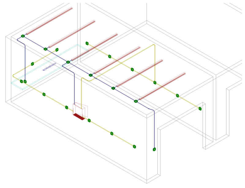
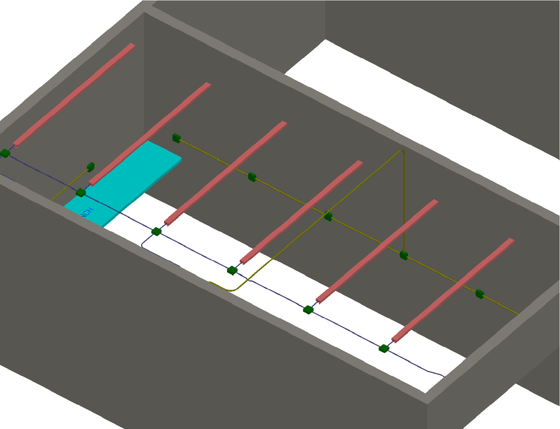
If all goes right, you should end up with something like this. The blue/purple conduit is for lighting and it's all in 1/2" pipe. The yellow is power and in this drawing is all 3/4" pipe.
There's only one saddle, a 3-point saddle in the lighting conduit that crosses the 3/4" power conduit. It's always easier to bend the smaller pipe so install the larger pipe first. And there's one kick in that same run that goes to the wall switch. Sometimes you have to kick a 90 over because there's not enough distance to allow for a full 90 bend. Everything else is 90 bends.
I ran a pipe across the ceiling for the power to feed the 240V TS first, then go either way for the convenience outlets. While taking the conduit all the way around the wall would have been easier, the wire pull would be tougher and any future additions would be more problematic.
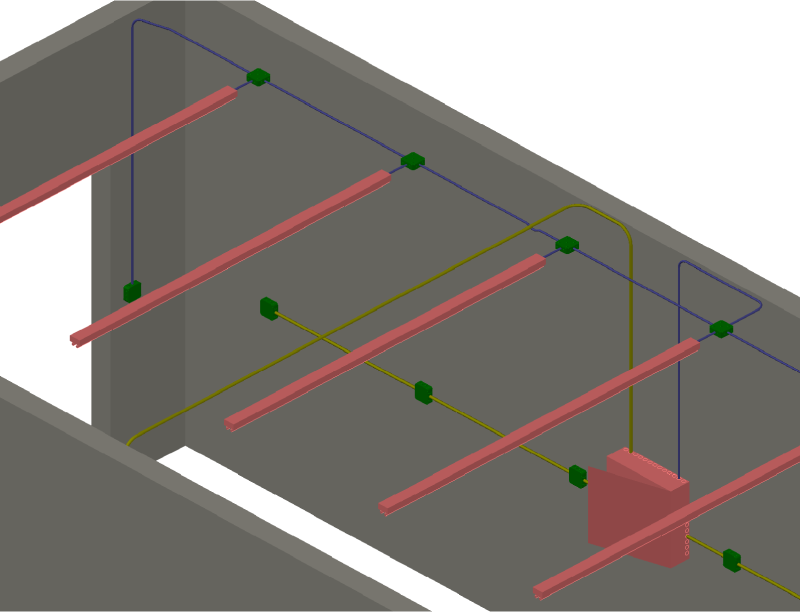
Closeup in 3D. Purple = 1/2" conduit. Dark yellow = 3/4" conduit.